
|
|
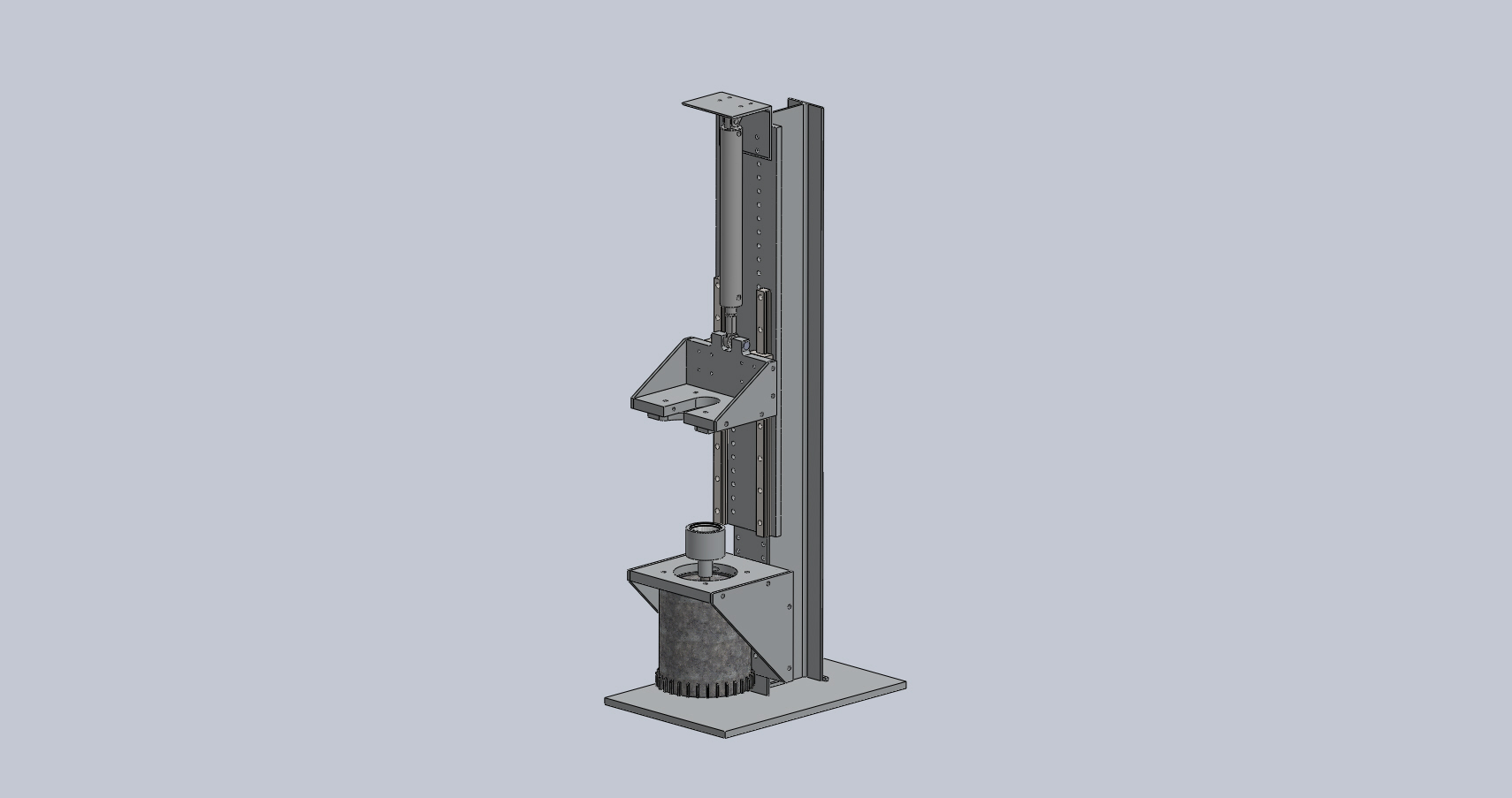
video of the spinwelder in action! First, I designed the entire machine in Solidworks incorporating some parts that we already had to save on cost. 
The machine ended up looking a lot like the drawing.... maybe it's because I actually used the solidworks drawing to machine the parts... 
Well, now that I've got your attention I'll fill you in on how and why I built this machine. So, I work for a company that used to make the water games that you see at the fair, I started working there laying vinyl decals, but that's another story... one day The owner decided that he wanted to get into the business of LED ferris wheel lights, He put me in charge as the head engineer of the project, I designed a waterproof impactproof polycarbonate lens/case for the circuit board. Our board mixes very bright red green and blue LEDs to acheive a serial controlled 256 color light, these lights are all wired to a serial data system back to the controller which allows the lights to play out patterns in the form of frames. You can see videos of the original lights Here they are pretty amazing. those lights needed to be glued together, as they are oblong and therefore can not be spinwelded. You can check out a page about the CNC gluing machine that I built for that, Here the lights went over great and are in use on tons of rides at carnivals and fairs in multiple countries. we decided we needed a small light for direct replacement of incandescent lights utilizing the same mounting holes, and thus the "Tsegment" was created. the T representing the resemblence of the incandescent "turbolights" they were to replace and segment (nonplural) meaning the light was to be programmed as a single segment, unlike the normal oblong lights, which are programmed as two segments, for more resolution. with our regular lights, much of the production time is spent gluing the lenses together, and also this high strength glue is expensive, so on our new lights we were investigating sealing techniques when we discovered spin welding. I did a few prototypes using a drillpress and experimented with joint design... 
when we saw how much spin welding machines cost, we decided to build our own, hey if we can build a CNC glue machine we can make a spinwelder right? I was put as head engineer for the spinwelding machine, as my CNC glue machine had matured and was running smoothly. I first designed two lenses to match our new 2" round circuit board, in the same style as our normal light, a normal 2" tall lens and a low profile 5/8" lens for clearance applications. 
we wanted to incorporate some parts we already had to save on costs.... theory of operation a 3 phase motor will spin the lens at a certain speed, then a pneumatic ram will push the base against the bottom of the lens, creating friction and melting the two plastic pieces together, when the bond is made, friction drastically increases, setting off the overtourque detection in the 3 phase controller. the motor is stopped and the ram is retracted, leaving a perfectly sealed part. we used a 3 phase motor from a water pump we already had and a programmable 3 phase controller we had. I interfaced this with a programmable logic controller we had laying around, this is used to check the safety sensors and run the air solenoid. we bought an appropriate air ram and valve we machined all of the metal for the mounts and used a piece of linear sliderail left over from the CNC glue machine |
Home |
|
|
|
| Copyright 2011 AK Motorsports
Sarasota, FL USA |