| How To | 03/02/2012 |
Delco GM radio DM165 Audio amp repair
(And where to connect line level outputs for an external amp)
| How To | 03/02/2012 |
If you have an 80's though mid 90's Delco GM radio that has at least one speaker channel entirely out, or makes a popping or static noise, here is how to fix it.
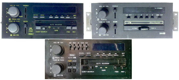
 (Click for larger Picture)
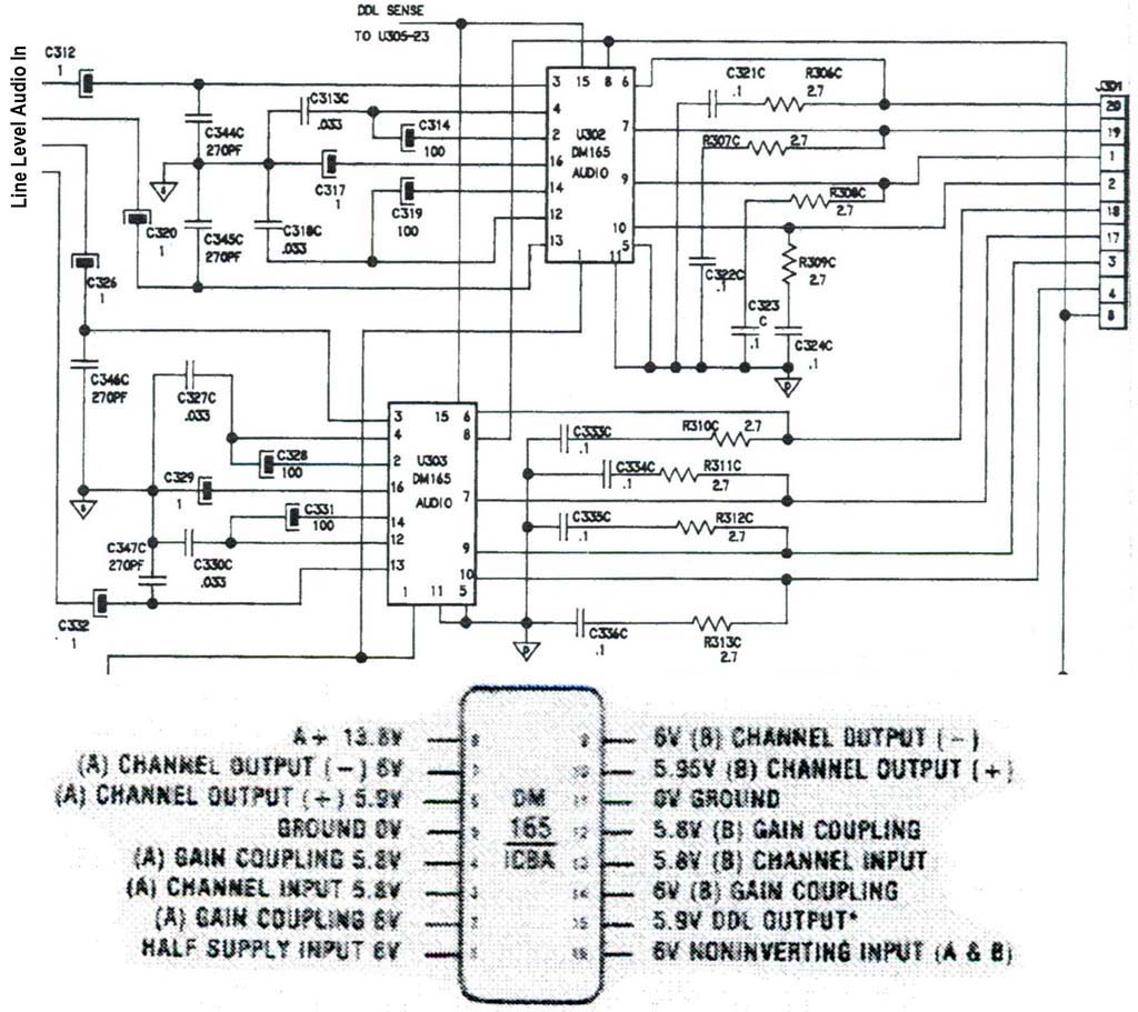
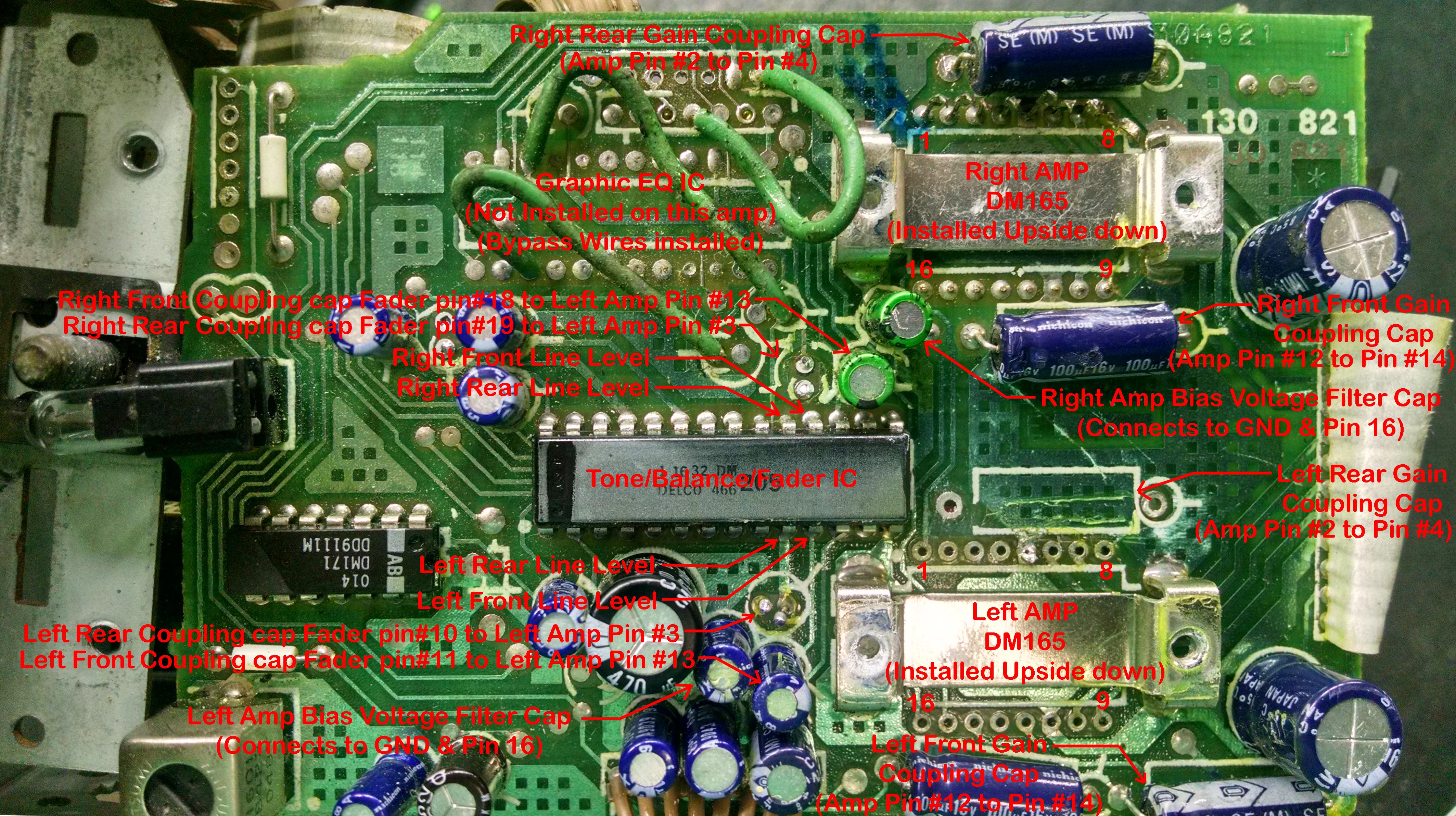
One DM165 is for the front and rear left speakers, the other DM165 is for the front and rear right speakers. This way each DM165 drives a 10ohm front speaker, which requires very little power, and a 4 ohm rear speaker. I think they also did this to prevent left and right channel cross talk. |
has the best price on all auto parts, and their service is great. 
|
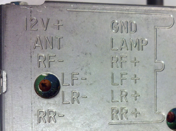 '82-'87 Pinout
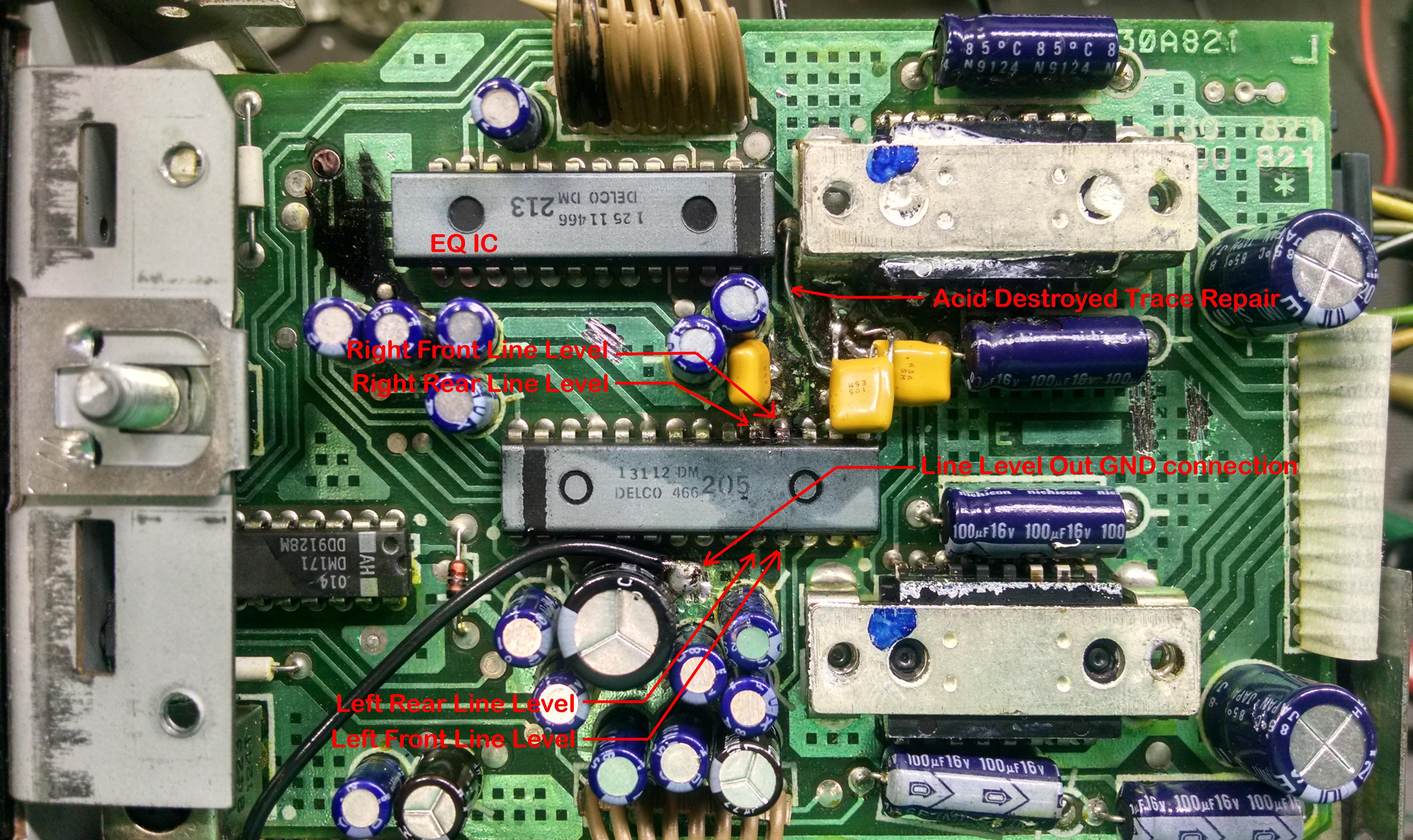 (Click for larger Picture)
Final Thought - The GM radios aren't super powerful, but if trying to keep keep or make your GM car or truck all original, this is the only way to get a radio that works. Even the radios that you get out of the junkyard will need at least one of the DM165's replace. Now you know how to do it. Have fun with your working radio.